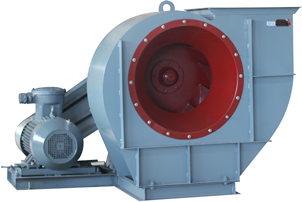
1. There are four types of transmission modes for fans: A, B, C, and D. Type A transmission is used for No. 2.8~5, Type A transmission is used for No. 6, which has both Type A and Type C transmission. Type C and D transmission are used for No. 8~12, and Type B transmission is used for No. 16~20;
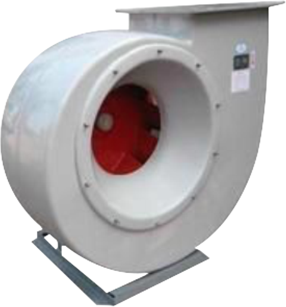
2. The ventilation fans N2.8A~6A are mainly composed of impellers, casings, air inlets, motors, and other parts. In addition to the above structure, the No6C and N8~20 also have transmission parts;
3. Impeller: composed of 10 backward tilting airfoil blades, curved wheel covers, and flat rear plates, made of steel plates or cast aluminum alloys. After dynamic and static balance correction and overspeed operation experiments, it has high efficiency, stable and reliable operation, and good air performance;
4. Chassis: Made in two different types, with the No2.8~12 cases made as a whole and cannot be disassembled. The casing of No16~20 is made into a three open type, with the upper half vertically divided into two halves along the centerline, in addition to being horizontally divided into two halves. It is connected by bolts for easy installation and maintenance of the impeller;
5. Air inlet: made into a whole structure and installed on one side of the fan, with a curved cross-section parallel to the axial direction. Its function is to allow the airflow to enter the impeller smoothly with minimal loss;
6. Transmission: composed of spindle, bearing box, rolling bearings, pulley or coupling;
7. Steel pipe or cable wiring, with grounding screws installed inside and outside the motor casing;